Laser-cut Fresnel spotlight
A handheld 1.6 Mcd, 2,000-lumen spotlight with a 200 mm Fresnel lens, a parametric laser-cut body and an Arduino-supervised 3S battery pack. First place, Machine Made, BLF 13th Old Lumens contest.
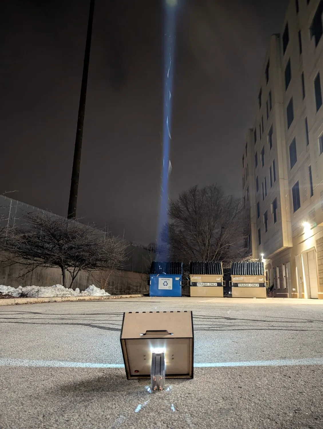
From the README
The Whats-That-Over-There-Inator 5000
A handheld 1.6 Mcd, 2,000-lumen spotlight built around a Luminus SFT-42R and a 200 mm Fresnel lens, with a laser-cut MDF body and a Seeeduino Nano acting as a 3S battery management system.
1st place, Machine Made category – BudgetLightForum 13th Annual Old Lumens Contest (2025) Build thread: Ruckusmattster's 13th Old Lumens Entry – Machine Made
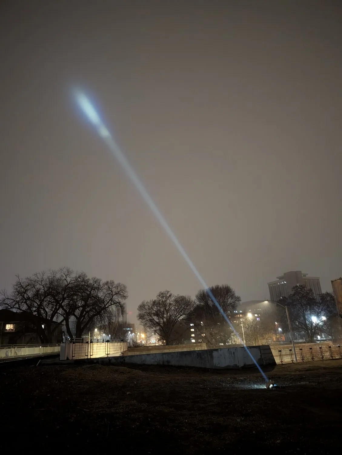
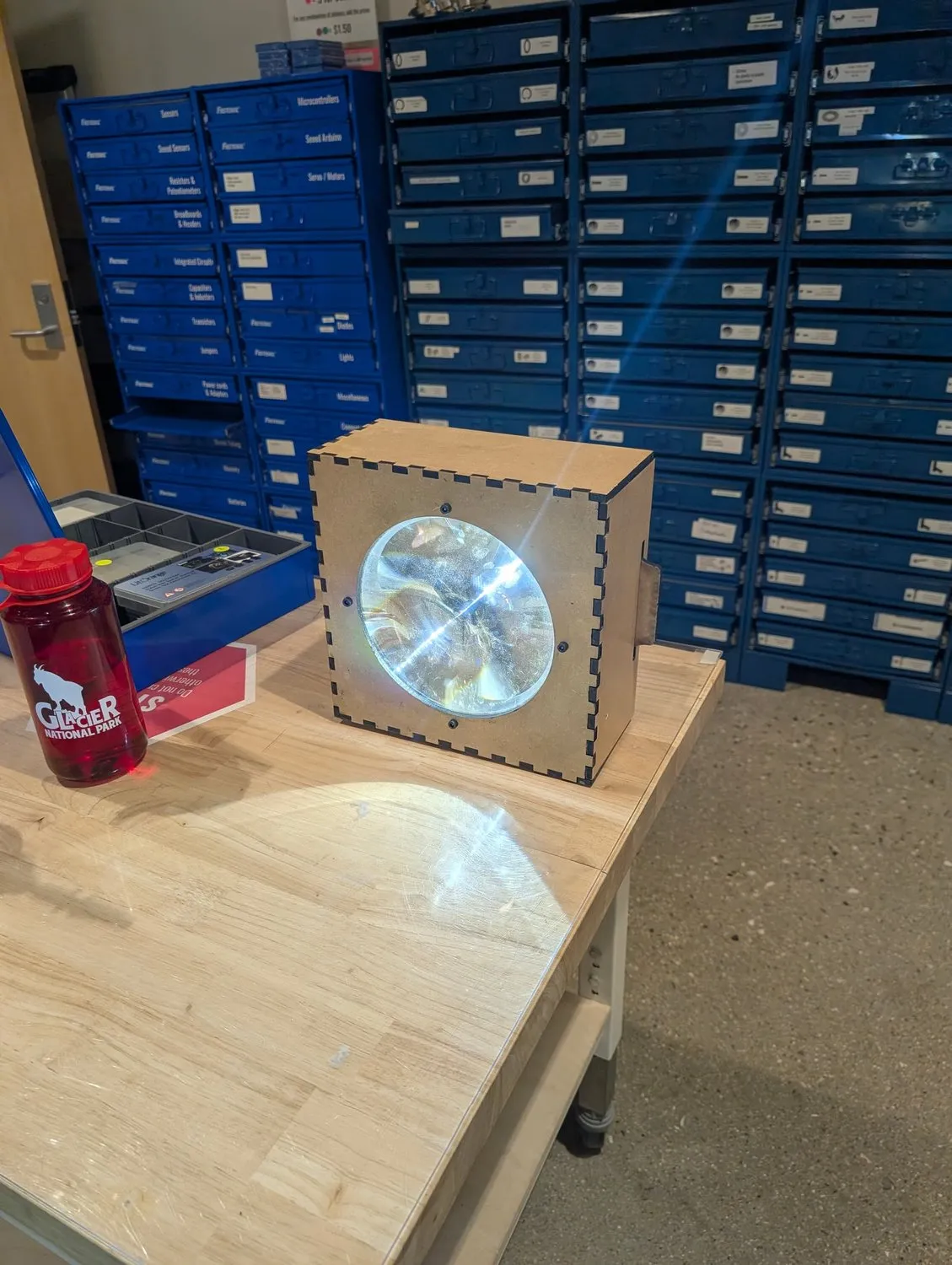
Specifications
| Peak intensity | 1.6 Mcd (≈2.5 km ANSI FL1 throw) |
| Output | ~2,000 lumens |
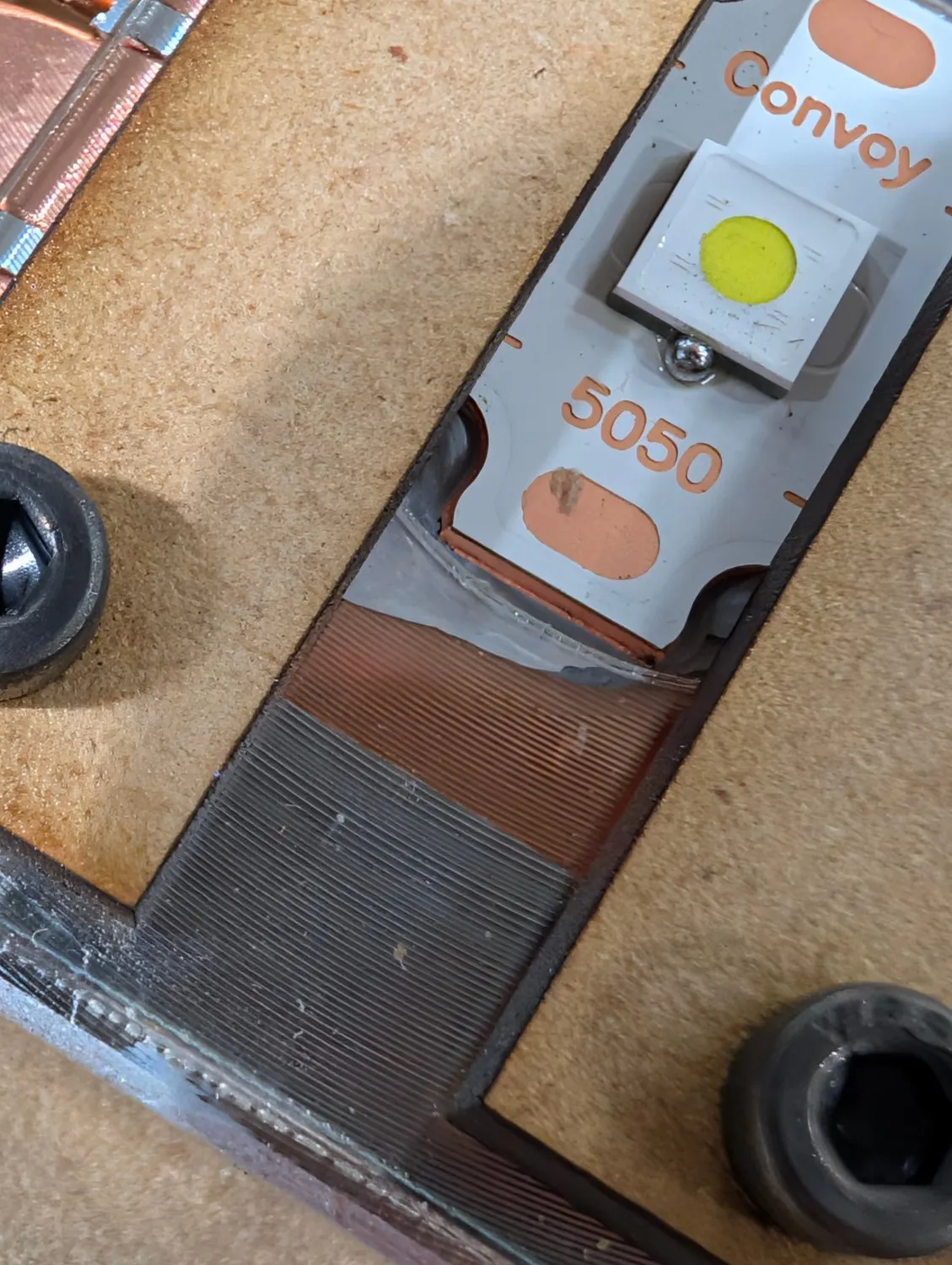
| LED | Luminus SFT-42R, 6500 K, on a Convoy 5050 copper board |
| Optic | 200 mm diameter Fresnel lens, 70 mm focal length |
| Drive current | 8.5 A constant current (~60% of the LED's potential) |
| Battery | 3S1P Samsung 50E 21700 |
| Protection | Seeeduino Nano per-cell monitoring (3.00–4.25 V), switching the pack through an automotive relay |
| Cooling | Tower CPU air cooler |
| Body | 1/4" laser-cut MDF, 150 W CO₂ laser |
| CAD | Fully parametric Onshape model |
The 1.6 Mcd reading was taken before the LED was properly focused, so the focused value may be higher.
How it works
Optics
The SFT-42R sits at the focal point of the Fresnel lens, so the lens collimates it into a tight beam. Focus is extremely sensitive: moving the LED just 1.6 mm visibly changes the beam from collimated to converging-then-diverging. Laser-cut centering rings locate both the LED and the lens, which removes the guesswork from alignment during assembly.
Details and the thin-lens maths: docs/optics.md
Power path
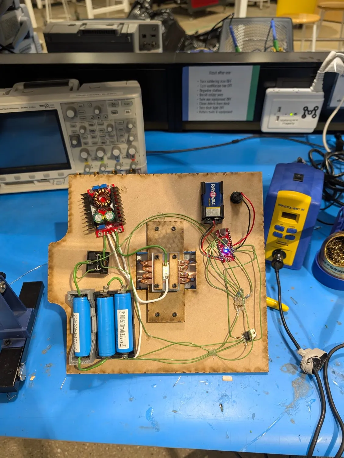
- The Seeeduino Nano measures every cell voltage in the 3S pack through resistor dividers.
- When the power switch is on and every cell is between 3.00 V and 4.25 V, the Nano turns on a MOSFET.
- The MOSFET energises the coil of a JD1912 automotive relay (with a flyback diode).
- The relay connects the pack to a CC/CV buck-boost module set to 8.5 A with a 3.5 V ceiling, which drives the LED.
The Nano runs from its own separate 9 V battery.
Details: docs/electronics.md · Firmware: firmware/
Enclosure
- Entire body cut from 1/4" MDF on a 150 W CO₂ laser, joined with finger joints.
- Every dimension in the Onshape model is driven by variables, so you can rescale it for a different lens diameter, focal length, PCB thickness or material thickness.
- All electronics mount to one back panel, so everything can be removed and tested with nothing in the way.
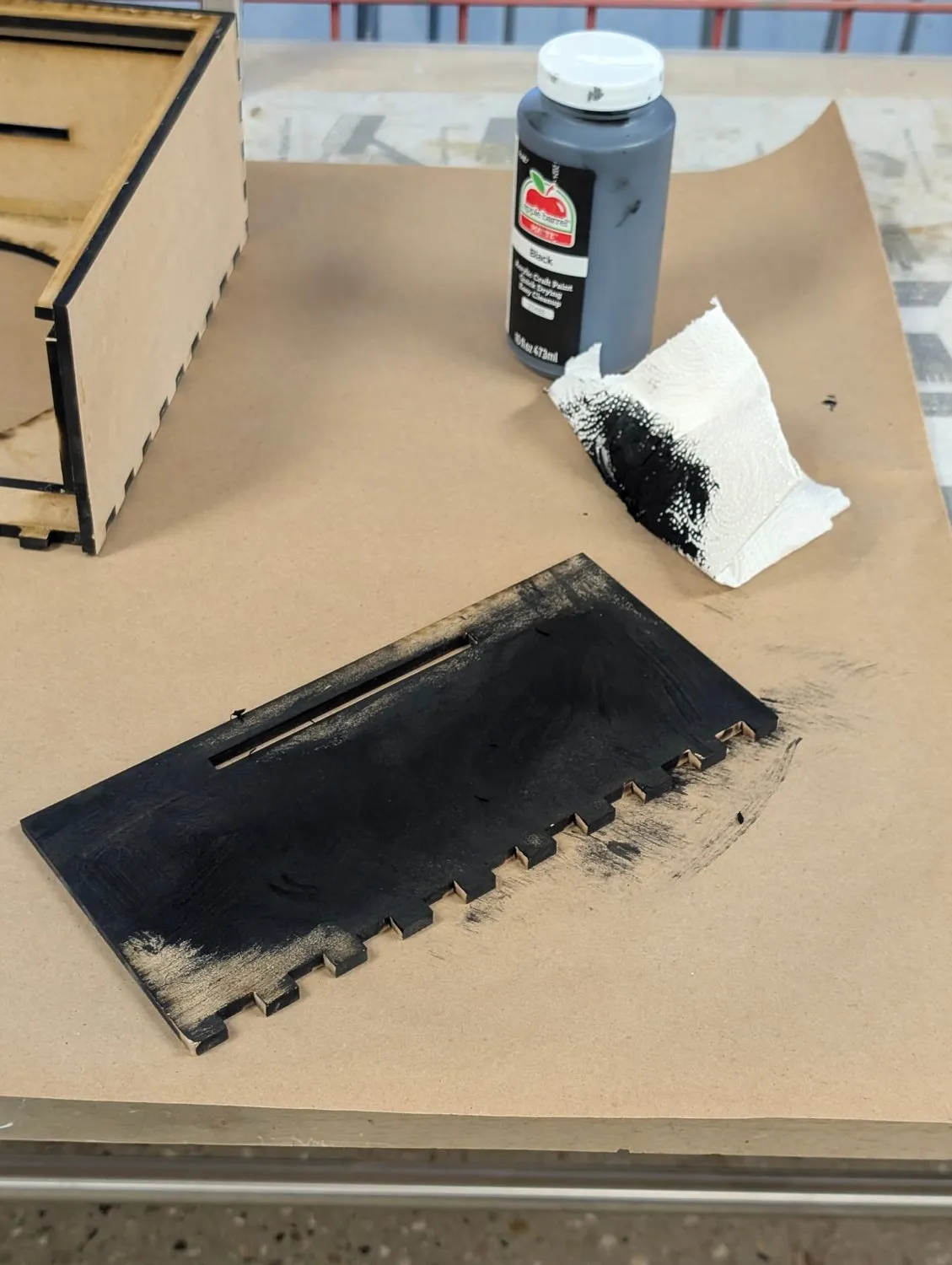
- Interior faces are painted black to reduce beam artifacts. Exterior faces are sanded and sealed with a water-based finish, and the front text is laser-engraved.
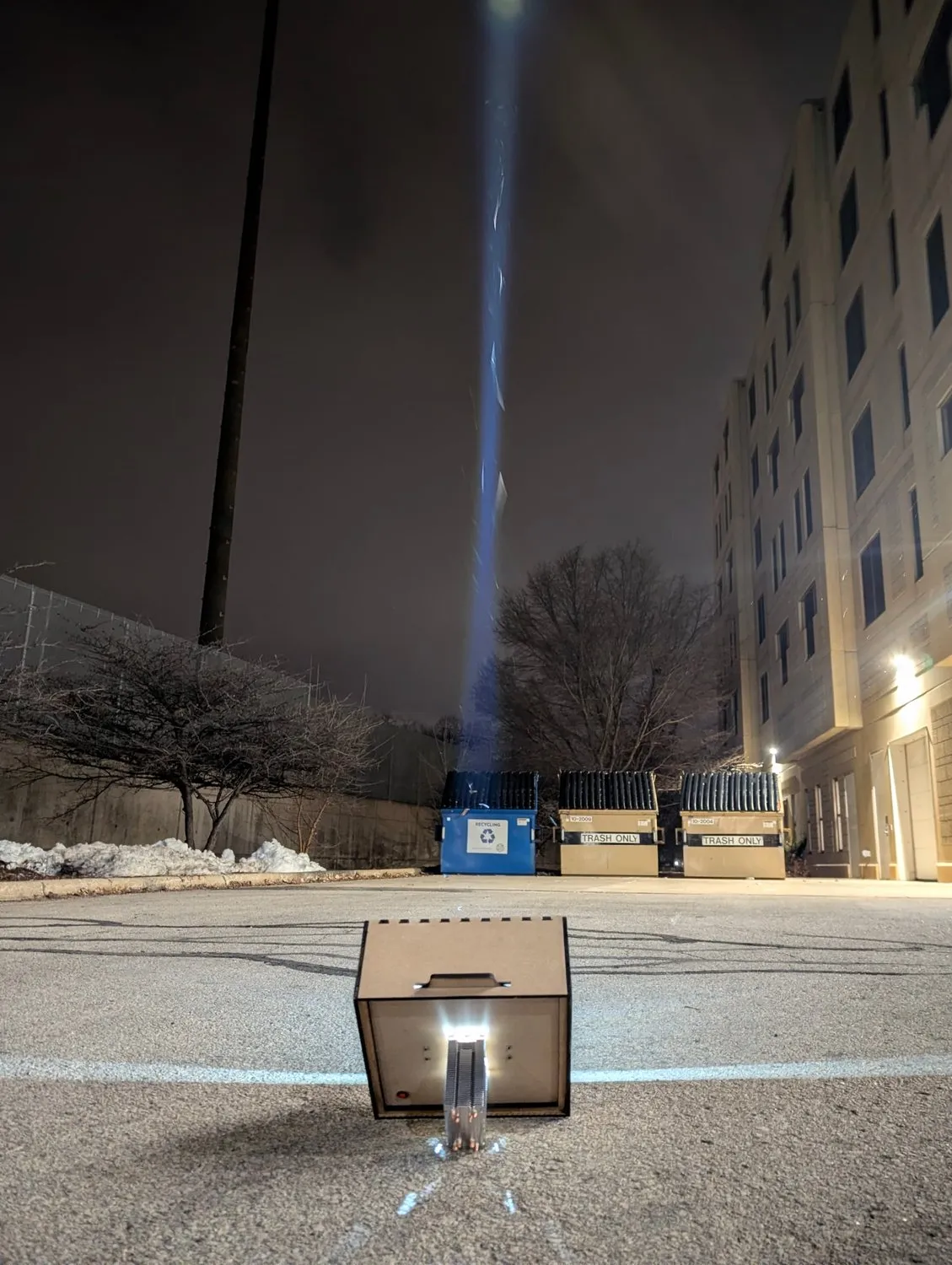
- The CPU cooler sticks out far enough that the light stands unsupported, either horizontally or pointed at the sky.
Build it yourself
- Copy the Onshape document and set the variables to match your lens, material and cooler.
- Use the calculated offset variable to handle the hard-to-calculate adjustments. The model assumes the same CPU cooler, so a different cooler needs this offset changed.
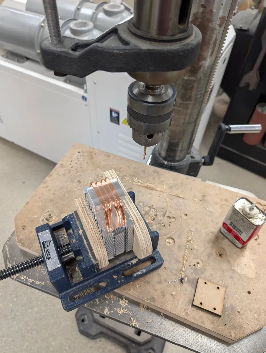
- Export the flat parts and laser cut them. A laser-cut drilling jig marks the heatsink mounting holes.
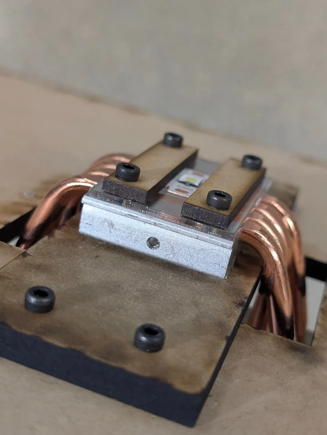
- Assemble the LED mount: a 1/16" PETG centering ring plus two laser-cut MDF pieces clamp the LED to the cooler with thermal paste. The heatsink screws go into a wooden block that bolts to the back panel.
- Wire the electronics on the back panel (see docs/electronics.md) and flash
firmware/bms/bms.ino. - Focus by adjusting the LED-to-lens spacing with shims. Check it in a dark room, ideally with fog or haze.
Full parts list: BOM.md
The electronics aren't specific to this build. Any way you choose to drive the LED will work.
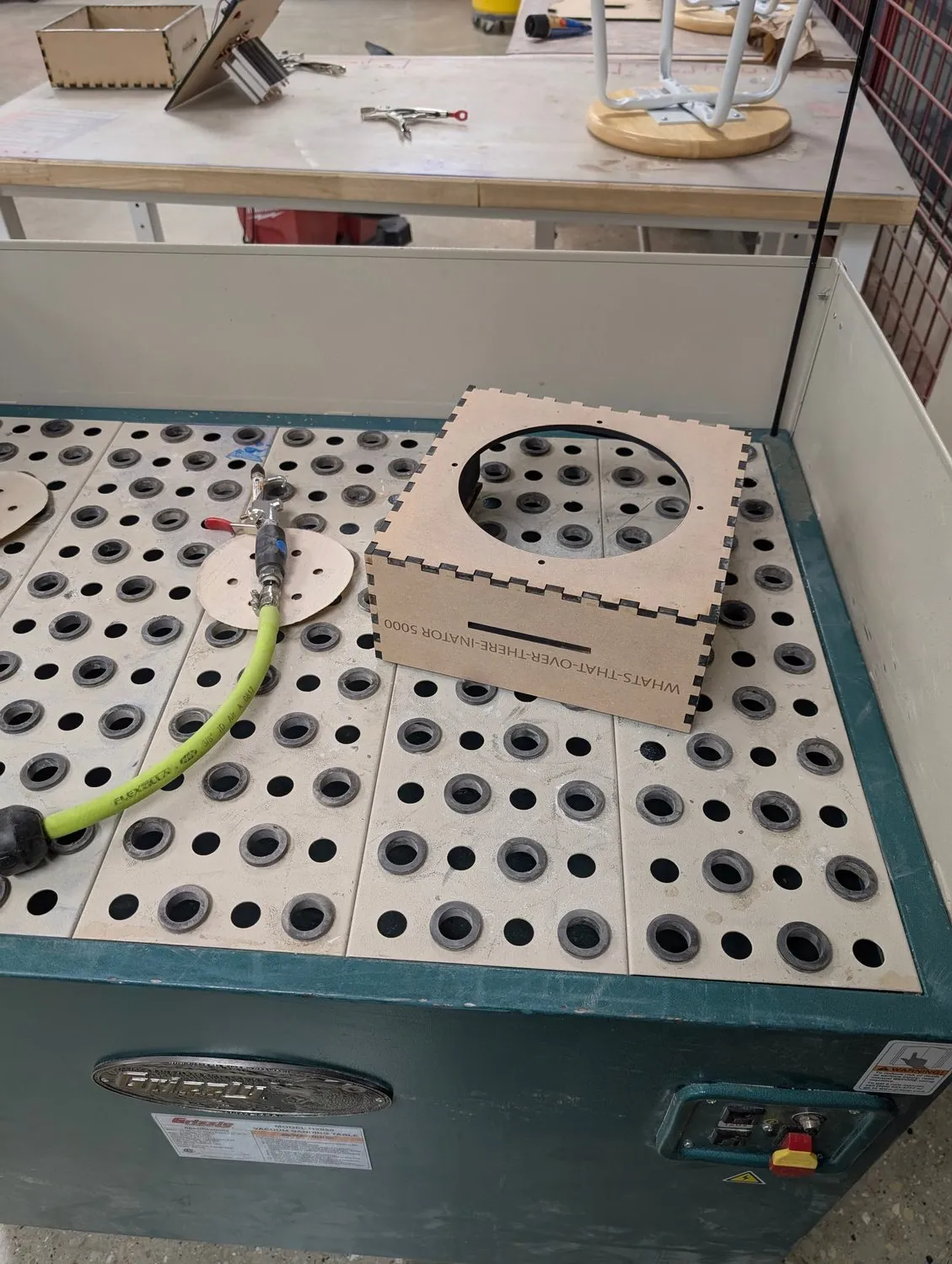
Lessons learned and future improvements
- Driver current. The buck-boost module tops out at 8.5 A, which leaves the SFT-42R at about 60% brightness. The target is around 13 A, with a module rated for 15 A.
- LED mount. Two 1/8" MDF pieces are probably the main source of beam artifacts. Sheet metal would be better.
- Assembly access. There's very little room to hold the nuts that mount the heatsink. Tapped holes in the heatsink would fix this.
- Focus adjustment. Shimming works, but you need very thin shims to get it exact. A planned alternative: a spring-tensioned screw through a threaded hole in the heatsink sets the position, then screws through slots perpendicular to the lens lock it in place.
- Optical losses. Next step is measuring lens losses cheaply by heating an insulated metal target and comparing thermocouple readings with and without the lens.
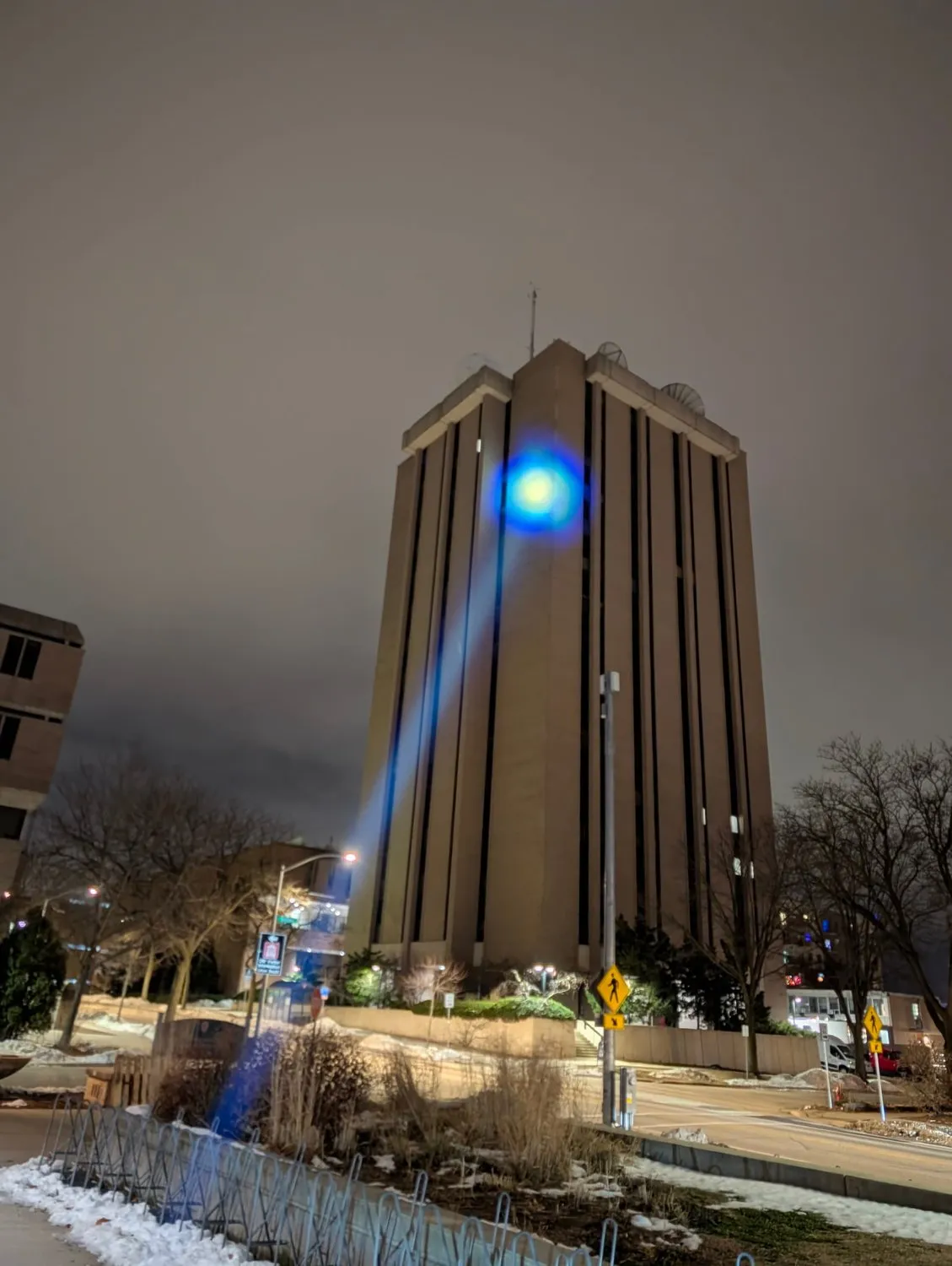
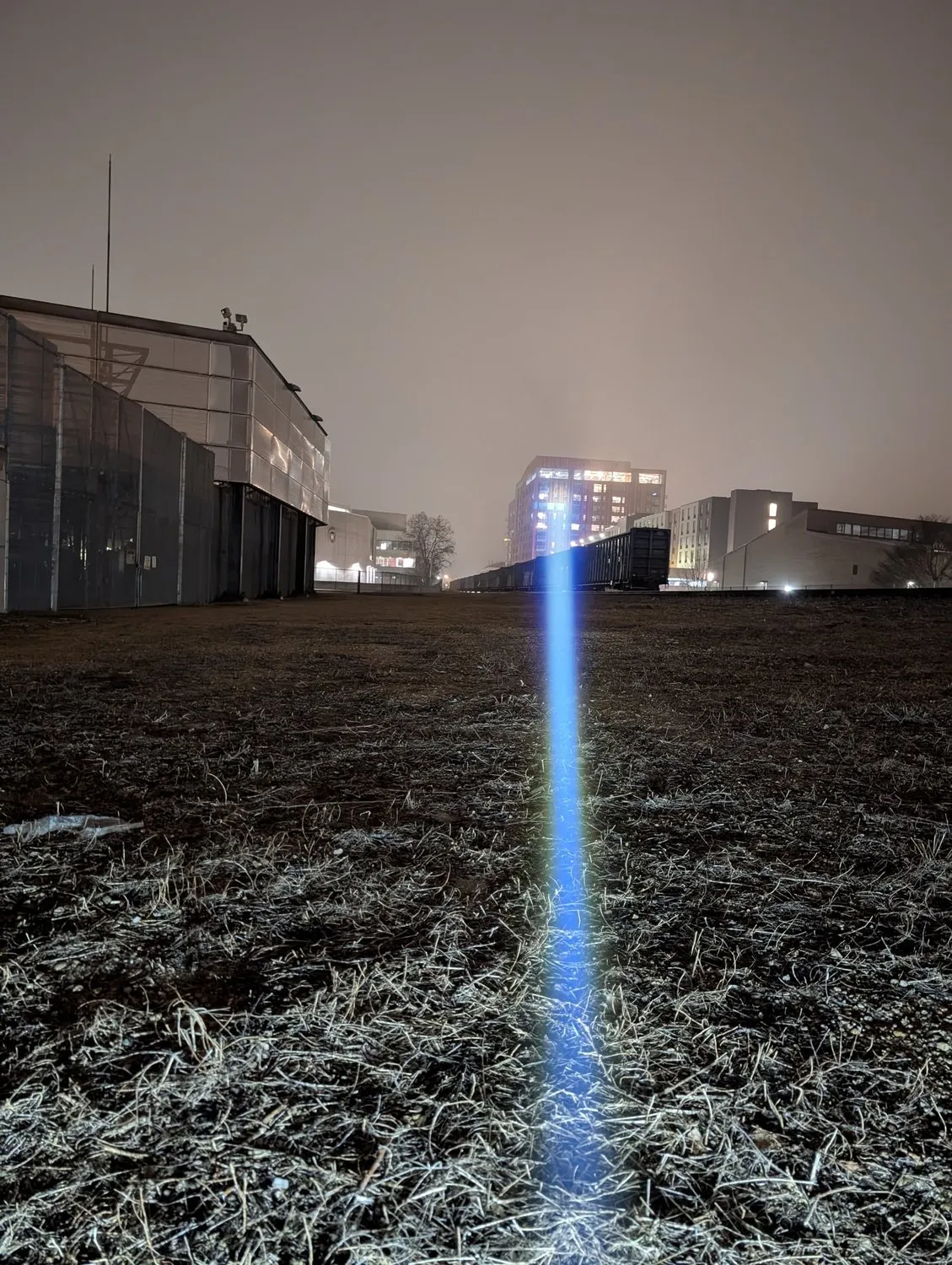
Beamshots
Credits
- A friend from the Badger Solar Racing team guided the BMS design, donated the cells, cell holder and relay, and helped characterise the cells.
- The BMS code was drafted with ChatGPT and reviewed by both of us.
- Thanks to the BudgetLightForum community for feedback in the build thread.